Grounding and Bonding Best Practices for Low-Voltage Installations
Grounding and bonding are the most overlooked disciplines in low-voltage system installation. A security integrator can select the finest cameras, the most reliable access control panels, and the fastest network switches, only to watch the entire system degrade because of hum bars on video feeds, phantom card reads, PoE switch failures during thunderstorms, and intermittent communication faults that defy diagnosis. In almost every case, the root cause traces back to improper or absent grounding and bonding.
This article provides a rigorous, standards-based treatment of telecommunications grounding and bonding per ANSI/TIA-607-C, explains the single-point ground philosophy that eliminates ground loops, and addresses the specific failure modes that grounding deficiencies cause in security, surveillance, and access control systems.
ANSI/TIA-607-C: The Telecommunications Grounding Standard
ANSI/TIA-607-C, Generic Telecommunications Bonding and Grounding for Customer Premises, is the definitive standard for grounding low-voltage infrastructure in commercial buildings. It defines a hierarchical bonding system that extends from the building's electrical service entrance to every telecommunications room, ensuring that all low-voltage equipment shares a common ground reference with minimal impedance.
The standard defines several key components that every integrator should understand and be able to identify on a building drawing or in the field.
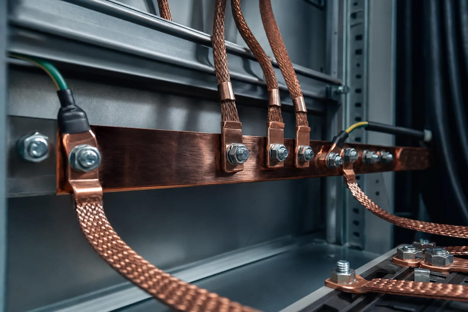
- TMGB (Telecommunications Main Grounding Busbar): Located at or near the building's main electrical service entrance, the TMGB is the central grounding point for the entire telecommunications infrastructure. It is bonded to the building's grounding electrode system with a conductor sized per NEC Article 250. Typically a wall-mounted copper busbar, minimum 6 mm thick, 100 mm wide, and as long as needed to accommodate all bonding conductors.
- TGB (Telecommunications Grounding Busbar): Installed in each telecommunications room (TR) or intermediate distribution frame (IDF), the TGB serves as the local grounding reference for all equipment in that room. Each TGB is bonded back to the TMGB via the TBB. The TGB is typically a smaller copper busbar mounted to the backboard or rack, pre-drilled for two-hole compression lugs.
- TBB (Telecommunications Bonding Backbone): The conductor that connects each TGB back to the TMGB. The TBB must be a continuous conductor with no splices, minimum #6 AWG copper, and sized per TIA-607-C Table 1 based on the distance from the TMGB. It runs vertically through the building's backbone pathway and is the single most critical conductor in the bonding system.
- BCT (Bonding Conductor for Telecommunications): Connects the TMGB to the building's grounding electrode system or the service entrance ground bus. This conductor must be sized per NEC 250.66, typically #3/0 AWG or larger for commercial buildings, and must take the most direct path with no unnecessary bends or coils.
Bonding Conductor Sizing per TIA-607-C
TIA-607-C specifies minimum bonding conductor sizes based on the type of connection and the distance involved. Undersized conductors increase impedance, which defeats the purpose of the bonding system by creating voltage differentials between ground references during transient events.
| Connection | Minimum Conductor Size | Conductor Type | Notes |
|---|---|---|---|
| BCT (TMGB to building ground) | #3/0 AWG typical | Copper, green insulated | Per NEC 250.66; size based on service entrance conductor |
| TBB (TGB to TMGB) | #6 AWG minimum | Copper, insulated or bare | No splices; upsize to #3/0 for runs exceeding 30 m |
| Equipment bonding jumper | #6 AWG minimum | Copper, green insulated | Rack/cabinet to TGB; keep under 3 m |
| Cable tray bonding | #6 AWG minimum | Copper, green insulated | Bond each tray section to TGB or continuous ground |
| Rack-to-rack bonding | #6 AWG minimum | Copper, green insulated | Bond all racks in a row to common horizontal bus |
All connections must use two-hole compression lugs on busbars, not mechanical set screws or wire nuts. This is not a suggestion but a requirement in TIA-607-C. Compression lugs provide a gas-tight connection that resists corrosion and maintains low impedance for the life of the installation. Set screws loosen over time due to thermal cycling and vibration, leading to high-impedance connections that appear to work during commissioning but fail under surge conditions.
Ground Loops: The Silent Destroyer of Video Quality
A ground loop forms when two pieces of equipment are connected to each other via a signal cable and are also each connected to ground at different physical locations with different ground potentials. The voltage difference between these ground points drives current through the cable shield, which induces noise on the signal conductors. In analog CCTV systems, this manifests as the classic rolling hum bar. In IP systems using PoE, ground loops can cause packet loss, CRC errors, and in severe cases, physical damage to the Ethernet PHY chip on the camera or the switch port.
The single-point grounding philosophy prescribed by TIA-607-C eliminates ground loops by ensuring that all equipment references the same ground point through the TBB/TMGB hierarchy. When a camera at one end of the building and a switch in the MDF both bond to their local TGBs, and those TGBs connect back to the same TMGB via dedicated TBBs, the potential difference between them approaches zero.
Field Diagnosis Tip
If you suspect a ground loop on an IP camera circuit, measure the DC voltage between the camera chassis and the nearest building steel using a high-impedance multimeter. Any reading above 1V DC indicates a significant ground potential difference. For analog systems, temporarily lifting the shield at the camera end (not the recorder end) will confirm a ground loop if the hum bar disappears. For permanent resolution, never lift shields. Instead, correct the bonding path so both endpoints share the same ground reference.
How Improper Grounding Destroys PoE Switches and Cameras
When a lightning strike or utility switching transient enters a building, the surge propagates along every conductive path it can find, including structured cabling, metallic conduit, cable trays, and building steel. In a properly bonded system per TIA-607-C, the surge energy is safely conducted to the grounding electrode system with minimal potential difference between any two points. In an improperly bonded system, the surge takes unpredictable paths through equipment, seeking the lowest-impedance route to earth.
PoE switches are particularly vulnerable because they have both data connections (Ethernet) and power delivery circuitry on the same ports. A transient voltage that enters through a camera's Ethernet cable and finds no proper bonding path will discharge through the switch's PoE controller IC, often destroying multiple ports simultaneously. We have documented cases where a single lightning event destroyed every port on a 24-port PoE switch because the outdoor cameras were not bonded to the building's telecommunications grounding system, and no Ethernet surge protection was installed.
Access control panels with RS-485 buses are equally susceptible. The differential signaling on RS-485 provides some common-mode noise rejection, but a transient exceeding the chipset's common-mode voltage range, typically plus or minus 7V for standard RS-485, will destroy the transceiver. When an RS-485 bus spans multiple buildings or runs through outdoor conduit, proper bonding and surge protection at each building entry point is mandatory.
Bonding Metallic Pathways and Cable Trays
NEC 250.96 and TIA-607-C both require that all metallic raceways, cable trays, and enclosures in the telecommunications pathway be bonded to the grounding system. This includes EMT conduit sections, cable tray segments, pull boxes, junction boxes, and equipment racks. Every metallic component that a low-voltage cable passes through or over must be bonded.
Cable tray sections are connected with bonding jumpers at each splice plate, and the entire tray run is bonded to the TGB in each TR it passes through. Use #6 AWG green insulated copper bonding jumpers with two-hole compression lugs. Do not rely on the tray splice plates alone for bonding continuity; the paint, anodizing, or corrosion on the splice hardware creates a high-impedance connection that will not safely conduct transient energy.
Testing and Verification
Grounding systems must be tested at installation and periodically thereafter. Use a ground impedance meter (fall-of-potential method or clamp-on ground tester) to verify that the building's grounding electrode system meets the 25-ohm maximum specified in NEC 250.53. For telecommunications grounding, the impedance from any TGB to the TMGB should be less than 1 ohm, and ideally less than 0.5 ohms. Document all measurements and include them in the as-built package.
Bonding continuity testing is equally important. Use a low-resistance ohmmeter (milliohm meter) to verify that each bonding conductor from rack to TGB, TGB to TMGB, and TMGB to building ground reads less than 0.1 ohms. Any reading above this threshold indicates a loose connection, corroded lug, or undersized conductor that must be corrected before the system is placed in service.
Getting Grounding Right the First Time
Proper grounding and bonding is not glamorous work, but it is foundational work. Every dollar spent on a robust TIA-607-C compliant bonding infrastructure pays for itself many times over in equipment longevity, video quality, system reliability, and protection against transient events. Retrofitting a grounding system after installation is exponentially more expensive than building it correctly from the start.
Zimy Electronics incorporates TIA-607-C grounding and bonding design into every low-voltage project we deliver. From TMGB and TGB busbar installation to bonding conductor routing, two-hole compression lug terminations, and post-installation impedance testing, Zimy Electronics ensures that every security infrastructure project is built on a solid electrical foundation that protects your investment for decades.