Designing the Network Backbone for a 500+ Camera Deployment
Designing a network for a handful of IP cameras is straightforward. Designing one for 500 or more is an entirely different discipline. At scale, every mistake compounds: an overlooked broadcast domain becomes a storm that crashes recording, a miscalculated PoE budget leaves cameras dark during a firmware push, and a single spanning-tree misconfiguration can take down an entire building's surveillance for minutes or hours. The network backbone is the invisible infrastructure that determines whether your video surveillance system is a reliable security tool or a fragile liability.
This article presents the architecture, protocols, and calculations required to build a production-grade network for large-scale IP camera deployments. These principles are drawn from real-world projects spanning corporate campuses, logistics hubs, healthcare systems, and municipal installations where uptime is measured against SLAs and failures have consequences.
Three-Tier Network Architecture: Core, Distribution, and Access
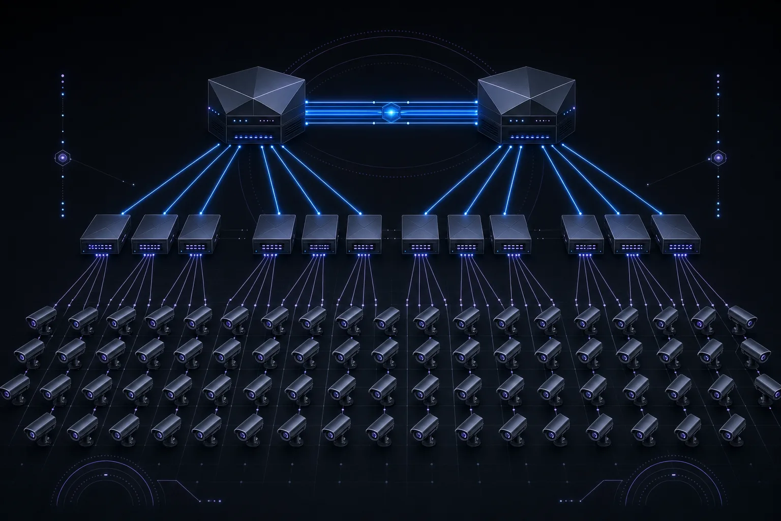
Any deployment exceeding approximately 100 cameras should abandon flat network topologies in favor of a three-tier hierarchical architecture. This is not theoretical best practice; it is the only way to maintain deterministic performance, fault isolation, and manageable troubleshooting at scale.
The access layer consists of PoE switches deployed in IDF closets or field enclosures close to the cameras. These switches provide power and connectivity to end devices. For a 500-camera deployment, you will typically have 15 to 25 access switches, each serving 24 to 48 cameras depending on port density and PoE class requirements. Choose switches with a non-blocking backplane and a PoE budget that accounts for every connected device at maximum draw plus 20% headroom.
The distribution layer aggregates uplinks from access switches and enforces policy. This is where inter-VLAN routing occurs, where access control lists (ACLs) are applied, and where IGMP querier functions reside. Distribution switches should be deployed in pairs with redundant uplinks to every access switch. Switch stacking (such as Cisco StackWise or Juniper Virtual Chassis) at this layer simplifies management but introduces a shared control plane risk. For mission-critical surveillance, chassis-based platforms like the Cisco Catalyst 9400 or Aruba 8400 series provide hardware-level redundancy with supervisory failover.
The core layer provides high-speed transport between distribution blocks and the storage/recording infrastructure. In a 500-camera system, the core handles aggregate throughput that can easily exceed 5 Gbps of sustained video traffic. Core switches must support wire-speed Layer 3 forwarding, 10GbE or higher uplinks, and sub-50ms convergence during failover events. The core connects to NVRs, VMS servers, and storage arrays, typically through dedicated 10GbE or 25GbE links.
VLAN Segmentation: Isolating Camera Traffic
Every camera should reside on an isolated VLAN that is separate from the production corporate network. This is not optional; it is a fundamental security and performance requirement. A properly segmented surveillance network uses a minimum of three VLANs:
- Camera VLAN (e.g., VLAN 100-109): All IP cameras reside here. No user devices or workstations should have access. Segment into multiple VLANs by building or zone to limit broadcast domains to 200 devices or fewer per VLAN.
- Management VLAN (e.g., VLAN 50): Used for switch management interfaces, camera configuration access, and SNMP polling. Restrict access via ACLs to authorized management stations only.
- Storage/Recording VLAN (e.g., VLAN 200): Dedicated to NVR-to-storage traffic (iSCSI or NFS). This VLAN should support jumbo frames (MTU 9000) and should never carry camera or management traffic.
Inter-VLAN routing between the camera VLAN and the recording VLAN should occur at the distribution layer, with ACLs that only permit the specific protocols needed: RTSP (TCP 554), ONVIF (TCP 80/443), and the VMS proprietary ports. All other traffic between VLANs should be explicitly denied.
IGMP Snooping and Multicast for Video Streams
Many VMS platforms use multicast to deliver video streams to multiple viewing clients simultaneously. Without proper multicast configuration, a single camera stream requested by three operators can consume triple the bandwidth as three independent unicast streams. Conversely, misconfigured multicast floods video traffic to every port on the VLAN, saturating access switches and causing packet loss.
Enable IGMP snooping on every switch in the video path. This allows the switch to examine IGMP join and leave messages and forward multicast traffic only to ports that have requested it. Configure the IGMP querier on the distribution layer switch for each camera VLAN. Without a querier, IGMP snooping tables will age out and multicast reverts to flooding. Set the IGMP query interval to 60 seconds and the group membership timeout to 260 seconds for surveillance workloads. If cameras span multiple distribution blocks, implement PIM-SM (Protocol Independent Multicast, Sparse Mode) at the core to manage multicast routing across Layer 3 boundaries.
QoS and DSCP Marking for Video Traffic Prioritization
Video surveillance traffic is latency-tolerant but loss-sensitive. A dropped frame in a recorded stream creates a gap in forensic evidence. Quality of Service policies should classify camera traffic and protect it from being starved by other network traffic, particularly on shared uplinks.
Mark camera traffic at the access layer with DSCP AF41 (Assured Forwarding class 4, low drop probability). This places video in a priority queue above best-effort traffic but below network control traffic (CS6/CS7). Configure weighted fair queuing (WFQ) or strict priority queuing on distribution and core uplinks, allocating a minimum of 60% of bandwidth to the AF4 class. NVR-to-storage iSCSI traffic on the storage VLAN should be marked DSCP AF31 and given its own queue allocation. Never mark surveillance traffic as EF (Expedited Forwarding); that class is reserved for real-time voice and should have strict policing that would drop bursty video.
Bandwidth Calculation: Sizing Uplinks Correctly
The single most common failure in large camera deployments is underestimating bandwidth requirements. Camera manufacturers often quote "average" bitrates that assume static scenes with minimal motion. Real-world bitrates in active environments like loading docks, retail floors, and transit stations can be 2 to 3 times higher than datasheet averages due to scene complexity, motion density, and I-frame intervals.
Bandwidth Per Camera: Common Configurations (H.265/HEVC)
| Resolution | FPS | Scene Complexity | Avg Bitrate | Peak Bitrate |
|---|---|---|---|---|
| 2 MP (1080p) | 15 fps | Low (hallway) | 2 Mbps | 4 Mbps |
| 2 MP (1080p) | 30 fps | Medium (lobby) | 4 Mbps | 8 Mbps |
| 4 MP (1440p) | 20 fps | Medium | 6 Mbps | 10 Mbps |
| 5 MP | 20 fps | High (parking lot) | 8 Mbps | 14 Mbps |
| 8 MP (4K) | 20 fps | Medium | 10 Mbps | 18 Mbps |
| 8 MP (4K) | 30 fps | High (retail floor) | 14 Mbps | 24 Mbps |
For a 500-camera deployment with a mix of 1080p and 4 MP cameras at an average of 6 Mbps, the aggregate sustained throughput is 3 Gbps. Factor in a 1.5x peak multiplier for simultaneous motion events (such as shift changes or evacuation drills), and you need uplinks capable of handling 4.5 Gbps. This demands a minimum of two 10GbE links from distribution to core using LACP for load balancing and redundancy.
Design Rule: Always Size for Peak, Not Average
Use this formula for uplink sizing: (Number of cameras x peak bitrate) x 1.2 headroom factor. For NVR uplinks, double the result to account for simultaneous recording and live viewing. If the calculated throughput exceeds 70% of your link capacity, upgrade to the next tier. A 10GbE link should not sustain more than 7 Gbps of video traffic; beyond that, micro-bursts will cause buffer overflows and frame drops.
Spanning Tree Protocol and Loop Prevention
Rapid Spanning Tree Protocol (RSTP, IEEE 802.1w) is mandatory on any surveillance network with redundant paths. Standard STP (802.1D) converges in 30 to 50 seconds, during which cameras lose connectivity and NVRs stop recording. RSTP converges in under 2 seconds in most topologies. Enable RSTP globally and configure the distribution switch as the root bridge with a priority of 4096. Set access switches to a higher priority (28672 or 32768) to prevent them from being elected root.
Enable BPDU Guard on every access port connected to a camera. If a camera is replaced with an unmanaged switch (an unfortunately common field practice), BPDU Guard will shut down the port immediately rather than allow a loop. Enable Root Guard on distribution switch downlink ports to prevent an access switch from ever being elected root. On ring topologies common in outdoor camera deployments, consider REP (Resilient Ethernet Protocol) or ERPS (ITU-T G.8032) for sub-50ms failover without the complexity of spanning tree.
Link Aggregation (LACP) for NVR Uplinks
Network Video Recorders and VMS servers are the heaviest consumers on the surveillance network. A single NVR recording 64 cameras at 8 Mbps average is ingesting 512 Mbps of sustained traffic. Add live viewing, playback, and video export operations, and a single 1GbE NIC is saturated. LACP (IEEE 802.3ad) bonds multiple physical links into a single logical channel, providing both increased throughput and link-level redundancy.
For NVRs handling 64 or more cameras, provision a 2x10GbE LACP bond as the minimum. Set the hashing algorithm to Layer 3+4 (source IP + destination port) to ensure traffic from different cameras distributes across both links. For the storage network between NVRs and a SAN or NAS, use a separate 2x10GbE or 2x25GbE LACP bond with jumbo frames enabled (MTU 9000). Verify that all intermediate switches, NICs, and storage controllers support the same MTU; a single device with a mismatched MTU will fragment frames and destroy throughput.
PoE Budget Planning Per Switch
PoE budget miscalculations are the second most common failure mode after bandwidth. A 48-port switch with an 800W PoE budget cannot power 48 cameras that each draw 25W under IEEE 802.3at (PoE+). That is 1,200W of demand against 800W of supply. When the budget is exceeded, the switch will deny power to lower-priority ports, and cameras go dark without any network-level alert unless SNMP traps are configured.
Catalog actual power draw per camera model, not just the PoE class. A PTZ camera with a heater and wiper may draw 60W (802.3bt Class 6), while a fixed mini-dome draws 12W. Add all devices on the switch including WAPs, intercoms, and door controllers. Multiply the total by 1.2 for the 20% headroom that accounts for power supply derating over temperature and aging. Select switches where the rated PoE budget exceeds this calculated value. For critical installations, choose switches with redundant power supplies rated for the full PoE load.
When to Deploy 25GbE or 40GbE Uplinks
10GbE is sufficient for most 500-camera deployments when properly designed with LACP and traffic engineering. However, certain scenarios justify 25GbE or 40GbE uplinks: deployments with more than 30% 4K cameras, systems with extensive AI analytics requiring full-resolution streams, or environments where video traffic shares a converged infrastructure with other enterprise services.
25GbE using SFP28 optics provides a cost-effective step up from 10GbE, as many modern distribution switches support 25GbE without a forklift upgrade. 40GbE (QSFP+) is typically reserved for core-to-storage links where multiple NVRs aggregate their write traffic to a centralized SAN. For truly massive deployments exceeding 1,000 cameras, consider 100GbE core links and a spine-leaf architecture that eliminates the distribution layer entirely.
Network Redundancy and Fault Tolerance
For surveillance networks, redundancy is not a luxury; it is the difference between maintaining continuous recording during a failure and losing critical footage. Dual-home every access switch to two distribution switches using RSTP or LACP. This ensures that a single distribution switch failure does not take down any cameras. Use VRRP or HSRP at the distribution layer to provide gateway redundancy for each camera VLAN.
For outdoor camera rings (parking structures, perimeter fence lines), deploy switches in a physical ring topology with ERPS or G.8032 for sub-50ms failover. Each switch in the ring should have enough uplink capacity to handle the total ring traffic in a worst-case cut scenario. Maintain a port density headroom of 20% on every switch to accommodate future camera additions without requiring new hardware.
Building It Right the First Time
A 500-camera network is a serious infrastructure project that demands the same engineering rigor as a data center deployment. The difference between a system that runs reliably for a decade and one that requires constant troubleshooting comes down to the upfront design: proper VLAN segmentation, correct bandwidth calculations, robust PoE budgeting, multicast optimization, and layered redundancy. Cut corners on the network, and every other component in the surveillance system suffers.
At Zimy Electronics, we design and deploy enterprise-grade network infrastructures for large-scale surveillance systems. Our engineering team handles the complete lifecycle from network architecture and switch configuration through commissioning and ongoing support. If you are planning a deployment that exceeds 100 cameras, talk to us before you buy a single switch. The network design phase is where projects are won or lost.